2SOLID AI — Product Design
Product Design
The physical half of intelligent products — industrial design, mechanical engineering, and 3D prototyping that turn a board and a firmware build into something people can hold.
Start a design§01 — Instrument
K u = F
the equilibrium the hero above solves live — a pin-jointed truss analyzed by the direct stiffness method
grown.js · Gaussian elimination, partial pivoting
Member width is proportional to |axial force| — tension drawn blue, compression amber. While the stiffness matrix is singular the lattice is a mechanism, and the scene says so rather than faking equilibrium.
§02 — The solver
Datasheet — the instrument, not a metaphor.
What runs behind this page is the same mathematics that sizes a real truss. Every quantity below is computed, not animated.
| 01Model | pin-jointed planar truss | two-force bar elements, pinned footings |
|---|---|---|
| 02Element stiffness | (EA/L)·cc^T | axial bar law, assembled over free DOFs |
| 03Solve | K u = F | Gaussian elimination with partial pivoting |
| 04Member width | ∝ |N| / |F| | axial force per unit applied load |
| 05Sign convention | N > 0 tension | N < 0 compression — colour-coded |
| 06Growth rule | Henneberg I | each new node welded with ≥ 2 non-collinear bars |
| 07Equilibrium audit | |ΣR + F| → 0 | support reactions summed every solve |
| 08Singular K | mechanism | drawn as dashed scaffolding until braced |
§03 — The argument
A product is a load path. Make it explicit.
Forces, tolerances, cost, ergonomics — every demand on a design resolves onto a member that must carry it. Our discipline is the one the hero performs: find the true load path, size what carries, erode what carries nothing.
§04 — Divisions
Two practices, one pipeline.
The surface people touch and the hardware under it — designed together, validated together.
Form & language
Industrial Design
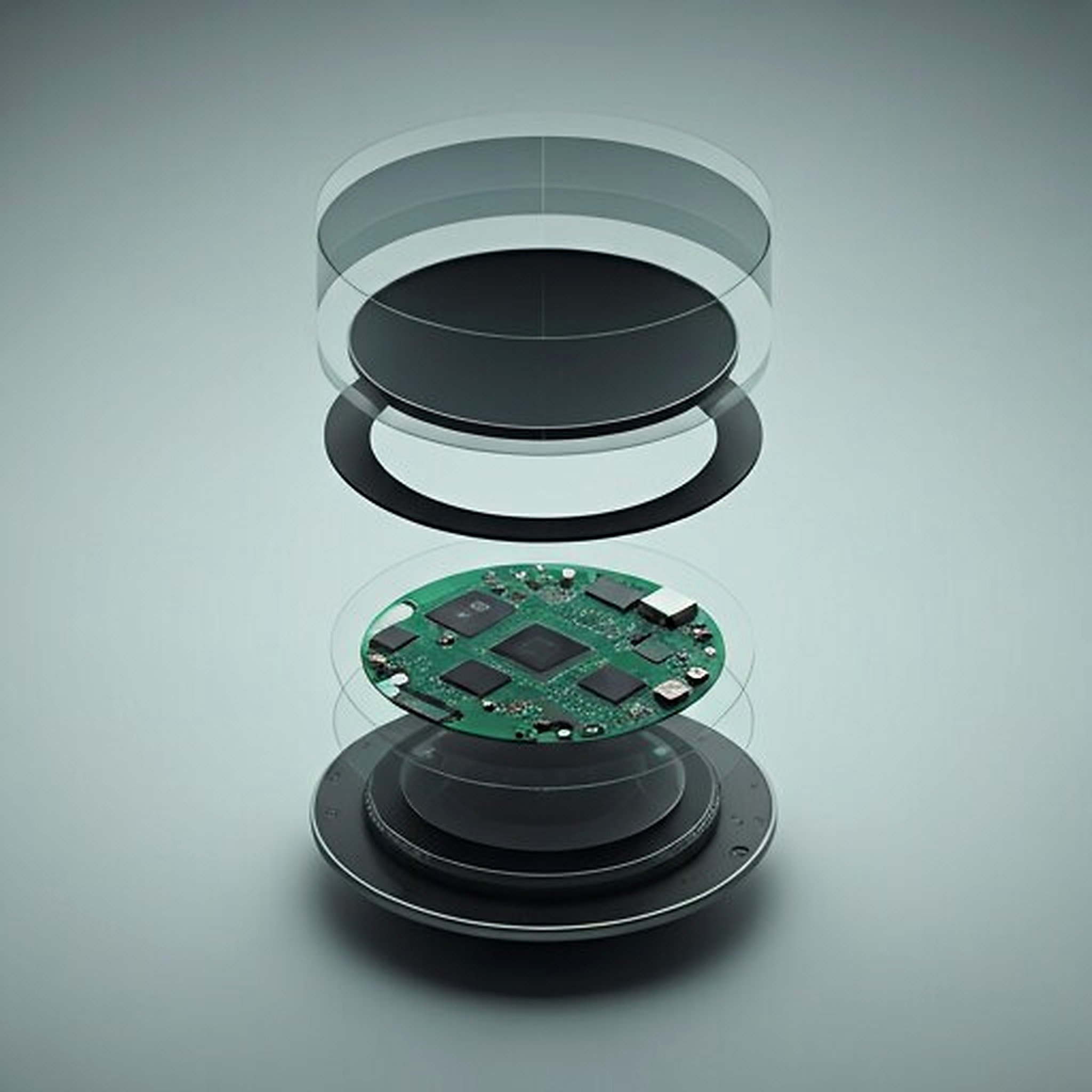
Product language, ergonomics, and design for manufacture — the Atelier 9 control node came through this practice.
Explore
CAD & validation
Mechanical & 3D Prototyping
Mechanical CAD, 3D printing, tolerance and assembly validation — iterate hardware fast before committing.
Explore
§05 — Pipeline: sketch → CAD → DFM → prototype → validation
01 · Concept & sketch
Form studies, ergonomic envelopes, and architecture options — breadth first, decisions recorded.
02 · CAD
Parametric solid models under controlled revision — the geometry is the master document.
03 · DFM
Draft, wall uniformity, tolerance analysis, process selection — the part is designed for its process, not adapted afterward.
04 · Prototype
Printed, machined, or assembled — each iteration built to answer a stated question, not to look finished.
05 · Validation
Assembly, fit, stack-up, and function — evidence recorded against the requirement, not the hope.
§06 — Deliverable classes
What a design engagement leaves behind.
Every stage produces a document class — the record trail from sketch to manufacturing package.
Concept → validated design
2SOLID AI · product design practice
- CONCEPT
Form studies, ergonomic envelopes, architecture options — reviewed and selected
- CAD
Parametric solid models, controlled revisions — the master geometry
- DFM REPORT
Draft, wall thickness, tolerance stack-up, process and material selection
- PROTOTYPE
Physical parts per iteration — each with the question it was built to answer
- VALIDATION
Assembly and test evidence — fit, function, tolerance stack verified
- TRANSFER
Manufacturing package — drawings, BOM, assembly notes, revision control
Have a product to design?
From concept sketch to production-ready files.