2SOLID AI — Engineering
PCB & Embedded
Software is only half of an intelligent product. We design the boards, write the firmware, and take hardware through bring-up — schematic to validated silicon.
Scope hardware§01 — SCOPE
Hardware obeys physics. So does this page.
The hero above is electrostatics done honestly: field lines integrated through a Coulomb field, equipotentials extracted by marching squares, your pointer acting as a live test charge. The boards get the same treatment — measured against datasheet, not hope.
§02 — CAPABILITIES
What we build
PCB design
Schematic capture, layout, and design for manufacture — prototype runs to production panels.
Firmware
Embedded firmware for control, sensing, and communication — versioned, tested, documented like software, because it is.
Bring-up & validation
First-article bring-up, test fixtures, and the evidence trail that proves the design works.
Connected devices
Devices that talk to software — telemetry, control surfaces, edge intelligence.
Enclosure & integration
Mechanical design and 3D prototyping with Product Design — board, box, and assembly.
AI at the edge
Models on-device where latency, power, or privacy demand it.
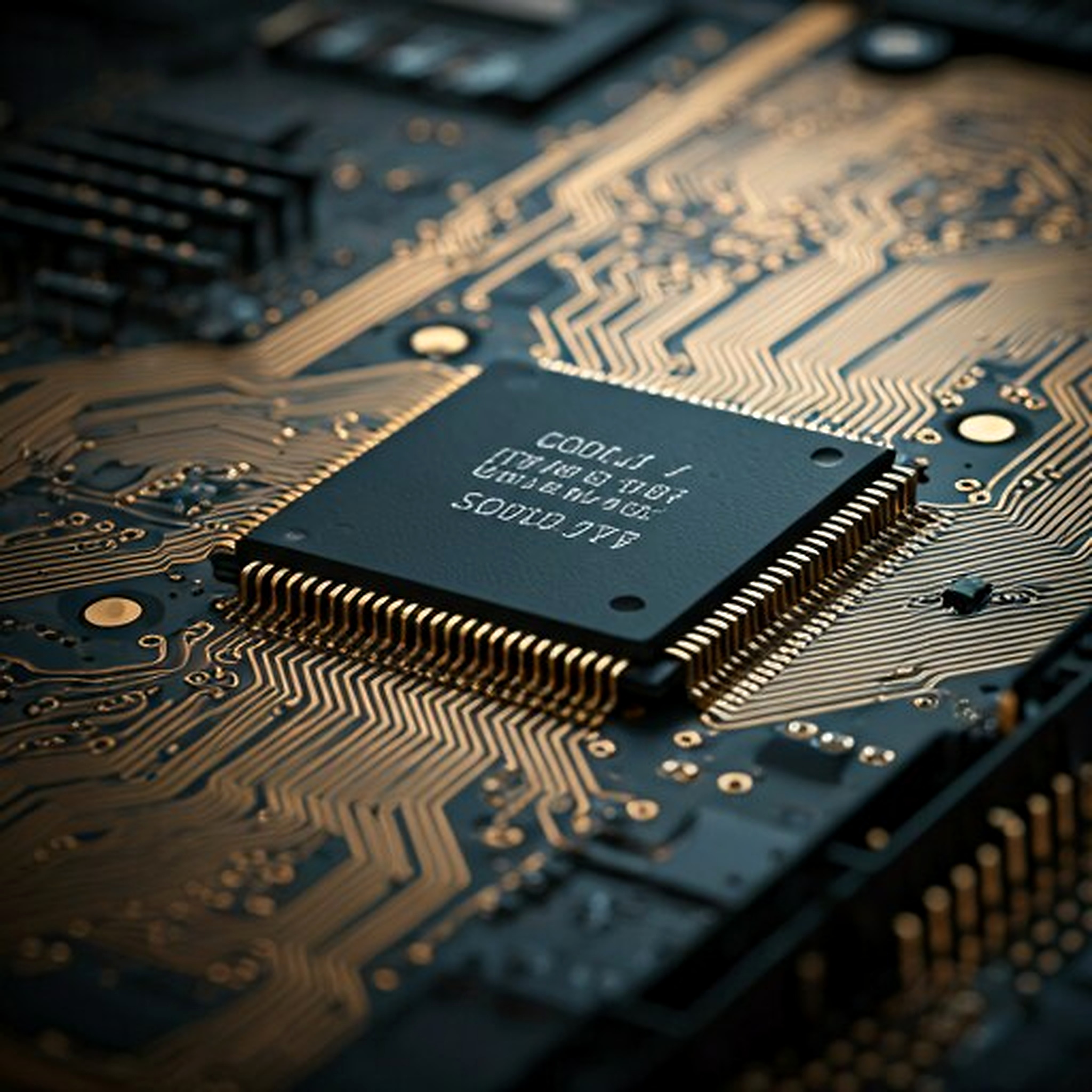
From schematic to shipping hardware
Our embedded work is the same discipline as our software — documented, reviewed, verified. Board layout, component selection, firmware, power design, and the validation rigs to prove it.
§03 — INSTRUMENT
The hero is a field solver. Here is its datasheet.
Five conductor charges, alternating polarity. Field lines are integrated live; equipotentials are true level sets, not drawn rings. Move your pointer — it enters the calculation.
| 01Electric field | E = Σᵢ qᵢ·r̂ᵢ/rᵢ² | Coulomb superposition over five conductor charges |
|---|---|---|
| 02Softening | ε² = 220px² | Plummer-softened — identical ε in field and potential |
| 03Potential | V = Σᵢ qᵢ/√(rᵢ² + ε²) | E = −∇V holds exactly for the drawn field |
| 04Equipotentials | marching squares | 14 px lattice · 36 px overscan · saddles by cell mean |
| 05Iso levels | 7 | V ∈ {−0.030 … +0.030} |
| 06Field lines | 10 seeds per + charge | Euler steps of 3.4 px · ≤160 steps · terminate at − charges |
| 07Probe | pointer = live test charge | re-bakes the V lattice and warps contours as you move |
§04 — MATERIALS & STANDARDS
Values a datasheet can be checked against.
The numbers we design to are published numbers. Verify them — that's the point of a datasheet.
| 01FR-4 dielectric constant | 4.2–4.8εr | at 1 MHz — laminate-dependent |
|---|---|---|
| 02FR-4 glass transition | 130–140°C | 170 °C and up for high-Tg variants |
| 03Copper weight, 1 oz | ≈35µm | nominal foil thickness |
| 04Controlled-impedance targets | 50 / 90 / 100Ω | single-ended · USB diff pair · Ethernet diff pair |
| 05Board acceptability | IPC-A-600 | acceptability of printed boards |
| 06Design standard | IPC-2221 | generic standard for printed board design |
| 07Soldered assemblies | J-STD-001 | requirements for soldered electrical assemblies |
| 08Flammability | UL 94V-0 | standard FR-4 laminate rating |
INVARIANT
E = −∇V
holds exactly in this hero — field and potential share ε² = 220 px²
emf.js · field() and potential()
A field that isn't the gradient of its own potential would be fiction. Same standard on the bench: measured, or it didn't happen.
§05 — PROTOCOL
First-article bring-up: power is applied last, not first.
Every board we ship has been through a staged bring-up. This is the sequence — each stage must pass before the next is energized.
First-article validation sequence
2SOLID AI · hardware validation
- S0 · VISUAL
Magnified inspection — joints, orientation, solder bridges, missing passives
before any power source touches the board
- S1 · RAILS
Continuity and rail-to-ground impedance — shorts caught cold
unpowered — the cheapest failure to find
- S2 · POWER-ON
Current-limited, sequenced — each rail measured against design spec
bench supply, not the wall adapter
- S3 · CLOCKS & RESET
Oscillators start, frequencies verified, reset lines behave
- S4 · COMMS
Buses enumerated — I²C, SPI, UART answer at the voltages they were designed for
- S5 · FIRMWARE
Flash, boot, telemetry — the board reports in
- S6 · FUNCTIONAL
The validation rig exercises the design — evidence logged and filed
the record, not the memory of it
Need hardware?
Board, firmware, enclosure — one team does all three, and documents all three.